This is one of the most unique projects that we have worked on.
Representatives from the General Mills plant in Albuquerque approached us stating they had an oven band that could not be run at full speed because the bands kept sliding off the rollers. They wanted us to perform a 3D Laser Scan to determine if all the components of the oven band were in alignment and if the rollers were perpendicular to the band.
The entire length of the band was approximately three-hundred feet. It consisted of a hopper where the dough was placed on the belt. The dough was then flattened into sheets by rollers. After the continuous sheets were made, they were cut into bars. The bars proceeded along the band where a row of ovens was used to bake the bars. When the baking was completed, the bars proceeded to coolers that lowered the temperature. The final stop on the trip was to where the bars were wrapped for boxing and shipping.
Since the band was for food production, it was in a sanitary “clean room”. We worked only when the band was shut down for regularly scheduled cleaning and maintenance; we were required to walk through a machine that sanitized hands and feet and we wore sanitary booties over our steel toe work boots. Full safety gear including hard hats and safety glasses were also required to be worn within the plant. The oven band was housed in a long narrow room with little space between the sides of the oven band and the walls. This lack of space, coupled with the length of the oven band, meant that several scans needed to be made on both sides of the band. We only had two days to work in every ten-day cycle.
After the initial site visit, our team met to discuss the challenges. After considering all options, we decided that “old fashioned” surveying was the best solution to this problem. The “old fashioned” technology consisted of a total station being used as a transit, a plumb bob, and a steel tape. We figured this would be faster and easier.
We presented our suggested methodology to the client and were given notice to proceed.
Tasks Performed:
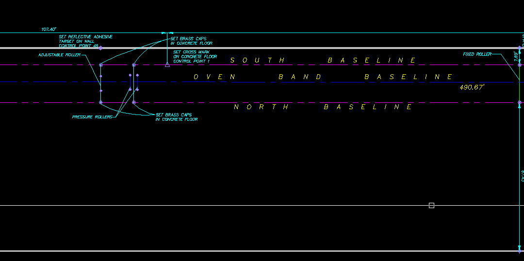
- After reviewing the oven band, we elected to establish a baseline off the south side of the south legs on the ovens. The baseline was 4.485 feet south of the south face of those legs and was based on a least squares best fit calculation of the shots we took on the legs.
- We then set control point number one at a random location on the baseline. We set reflective targets as reference marks on the west wall and the east frame.
- Off the south end spindle of each of the rollers, a plumb bob was placed down to the floor and the center of the roller was marked on the floor. The same thing was then done off the north spindles.
- A line was projected between the end of each spindle to the baseline. These points were measured using a steel tape; no calibration of the tape was necessary because the temperature in the room was 68 degrees Fahrenheit and because of the short distances being measured.
- We then calculated the angle between the baseline and the projected spindle line at each roller. The roller angles were not perpendicular to the baseline. We calculated the location of the perpendicular angle in relationship to the west end of the north roller and a new mark was made on the floor.
- We set up a Trimble VX spatial imaging station which was serviced and calibrated at Trimble Navigation in Denver, Colorado. We used a 16-ounce plumb bob with fishing line to center the instrument over the mark. A backsight reference was made on the reflective target on the north wall.
- A parallel baseline was established on the opposite side of the oven band. The spindles on that side were projected to the baseline. The perpendicular location was calculated, and a mark was made on the floor at each location.
- A shot was made at each point marked on the floor, as well as at the end of each spindle. After downloading the data into Trimble Business Center, the coordinates were exported to a text file. The text file coordinates were imported into Carlson Survey software. As drafting proceeded, it was noted that the spindles did not line up and that the rollers appeared to be different on each side.
- The next day we made detailed measurements and took shots on each roller. In measuring the adjustable roller, we realized that the pivot point was not the end of the spindle, but that it rotated about a location set in from the end of the spindle. General Mills personnel set the roller to its theoretical perpendicular point. This location was then measured and shot.
- This data was downloaded, exported and imported into the original drawing. A new baseline of the oven band was calculated based on the data. A line perpendicular to the baseline running through the center of each roller was calculated and that line was projected to the baselines on each side of the oven band. A coordinate was calculated at each of these intersecting points. The calculated coordinates were exported to a text file.
- The text file was uploaded into a data collector. We went back to the site and assembled the instrument and began to stakeout the location of each calculated point on the floor. Reference marks to each location were made. A hammer drill was used to make a hole in concrete floor. A flat top two-inch round brass cap with a three-inch spindle was set in concrete using a quick setting epoxy. Once the monument was set, the reference marks were used to mark the intersection point on the brass cap. A shot was made for verification and a punch was used to make a small mark in the brass cap at the location of the true perpendicular point. A total of six brass cap monuments were set.
- The spatial imaging station was then set up over each monument. A backsight was made to the reference point on the wall and a ninety or two-hundred-seventy-degree angle was turned towards the oven band.
- Marks were made on the frame of the oven band and on the floor. The purpose of these marks was to provide a reference point that General Mills personnel could use to place the rollers at the point perpendicular to the oven band baseline.
This solution worked and the client can now run the band at full speed, increasing output to the intended maximum.